Location and positioning in the railway (part 5)
RailLoc
Traditionally other sources of position have been used to supplement GNSS (including using Inertial Measurement units for navigation), if we had a more consistent version of the truth, we could flip this on its head and use this as the source and supplement with GNSS (and inertial) where this information is not available.
As it turns out, information is present and available all over the network which enables us to do this. By treating the problem as one of computer vision rather than positioning, we can take a completely new approach to the problem. By looking down at the 4-foot, it is possible to uniquely position ourselves by using the random structure of the infrastructure. This could be ballast structure, orientation of bolts, cracks and marks on sleepers - or all of these, basically anything visible. Obviously, these things change over time - but not as frequently as you might think and so given sufficient running, it’s possible to keep these up to date. For additional redundancy, fallback to traditional GNSS/Inertial gives a truly robust positional system - everywhere, even in GNSS denied areas.
What are the advantages of this approach?
Works everywhere - including GNSS denied areas like tunnels
Requires no boots on ballast, no installation or maintenance of the physical infrastructure
Works in near real time (we don’t have to wait for the end of shift to start processing)
Small footprint on the IM vehicle - simple installation
Can be transformed to any datum or representation, e.g., ETRS89 and/or linear references
Very high repeatability (relative accuracy)
Can inherit the absolute accuracy of an initial survey
Gives unambiguous position - this approach can definitively state that this is the correct track
There are potential disadvantages of this approach - but these can be mitigated relatively easily.
Infrastructure can change - this means that we may not be able to determine the track when it changes. This can be mitigated through the addition of a fallback to GNSS/Inertial, multiple systems running over the same piece of track to detect change as it gradually happens and therefore maintain the model
Requires installation on the train body - this is a small and simple installation and any vehicle being used for IM will require other systems and sensors to also be installed
Requires additional mapping - a recording to map the visual features to the network model is required. This can either be a bespoke run or could piggyback from a survey. For an initial IM run on a new track, the data can be positioned with a lag allowing for the correct attribution of the data. As such, this need not be a drawback, it can be done via existing processes and surveys
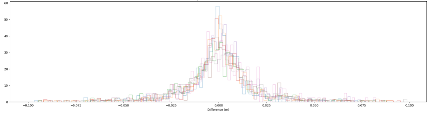
One of the additional benefits of this approach is how the errors manifest themselves, in effect, there are thousands of points of interest everywhere in the 4-foot, the more of these that we can “match” to, the lower the error. We don’t need to see all of the features every time - a few features can give us a position. When we don’t see any matching features, the gap can be bridged by using an IMU - or even GNSS if the gap is big enough to warrant. The errors also behave in a much more normal way, when we match features, the error is low and generally the more features the lower the error. This gives us something that we can’t definitively have with GNSS/INS – assurance of position, as the track effectively emits a unique signature, it is possible to state categorically that the vehicle being positioned is on track X.
Fault Navigator
This potentially still leaves an issue, we may have both an absolute reference for our IM data and also be able to understand the error bound in position between runs, but our maintenance worker still needs to be able to navigate to the faults. Let’s consider the four scenarios we covered earlier but this time using RailLoc as the positioning source:
A missing fastener on a piece of single track (i.e., one line only) in a nice open sky environment - the worker will be able to get near the fault using a handheld device and find it by walking up and down the track - the fault will be visible.
YesA top defect on a 4-track railway in a nice open sky environment - armed with a long/lat (with an error), the worker can use their handheld device to position themselves nearby - with an error. However, with RailLoc, the worker now knows for definite which line the fault was recorded on and so can derive the correct line and look for the defect (assuming it’s visible).
YesA minor gauge fault in a tunnel with two lines - with low levels of lighting and no source of position, the worker will find it harder to navigate to the defect, which, in itself, may be hard to see. Here the worker really needs more information, the worker knows which line the fault is on from the RailLoc data and using other sources (a distance from the tunnel portal could be derived from the RailLoc position for example) can estimate a linear distance to find the fault.
PotentiallyAn ultrasonic defect in an urban canyon area of railway with multiple tracks - because of interference such as multipath and/or possible lack of a GNSS signal, the error in the handheld device position will be large. The worker now knows which track they are on but realistically must test a large section of track to find the defect. They may be able to orient themselves with additional context around the RailLoc position (e.g., sets of points, other physical infrastructure) This may or may not be possible depending on the initial localisation that they can have (i.e., does their handheld device put them within range of the defect) and the time available to them on site.
Unsure
An absolute reference can mean different things to different people, it is really a feature or monument that is distinguishable from others by using some kind of measurement device (or by eye!). So typically, we think of an absolute measurement as a long/lat pair referenced to some datum (usually ETRS89 in the UK), this is easily transformable to a local grid reference. We need some other device to interpret this - usually some kind of GNSS receiver (with the errors having been discussed). A point can though, have multiple absolute references, as above an ETRS89 reference as well as a reference to the OS national grid; this could also be an offset along a bearing to a monument (such as a trig pillar). In the case of data captured alongside RailLoc, a further absolute reference is available, i.e., that of the underlying features that were captured by the system. As it turns out, we can make use of these features using a handheld device to help navigate a track worker to the same location.
This works in the same way as RailLoc, we use the device’s (e.g., mobile phone) camera to match features on the track to those stored in the map, we can then use this to localise ourselves in the feature reference space which in turn has a mapping back to absolute (ETRS89/OS) space.

So, using this app (Fault Navigator) the answer to our four problem statements now becomes YES for each one! In fact, if we think about the hardest problem of the 4, the ultrasonic measurement, then rather than test sections within a large range, the maintenance worker only need test within the range of relative error:

Where Re is the relative error, Te is the timing error between RailLoc and the Ultrasonic recording system and Fe is the feature matching error (from RailLoc and Fault Navigator combined). In practice, this number will be relatively small (a few cm), meaning that the worker can test a very short section to find the suspect/defect which obviously allows much more focussed testing over a much shorter time. The likelihood of them rejecting a suspect or confirming a defect is greatly increased with more accurate positioning. By reducing the area required for manual testing (or walkout), a worker is more likely to increase the amount of test passes (with ultrasonic testing equipment), this ultimately means a more definitive conclusion will be drawn from the testing - whether rejection of a suspect or validation of a defect.
With RailLoc, rather than the initial position being arbitrary or uncontrolled, we are able to survey it. This means that we can either piggyback on a Lidar (or similar) survey and wait for the fully processed positional output (this could take some time) or we use an inertial navigation system with PPK and match the position to a network model (either provided or this could be made as part of the process) which could have a relatively quick turnaround (within a day or two following the shift). This allows us to ensure (through a level of QC) that the path chosen through the model is correct and correctly attributed, but also understand (through statistics generated) the absolute accuracy of the resulting data. The benefit is that this is a one-time operation, any subsequent runs match to this one and inherit the absolute accuracy. For a typical survey of this kind, we can expect the absolute accuracy of the data to be a few centimetres - with outliers in very challenging GNSS denied environments. The important fact is that subsequent runs are placed in the same place every time - irrespective of any errors in the measurement (TG, OLE etc.) system. In fact, this approach makes it possible to place different datasets from different trains in the same position, time and time again, without the ambiguity of using an arbitrary reference run.